Getting Started
This guide will take you through the basic steps of importing medical images and generating a 3D model. It does not cover all features, but merely serves as an introduction to some of them.
You can create highly detailed 3D Anatomical models in 4 simple steps:
- Load CT/MRI Scan Images
- Select Tissue Type of Interest, e.g. Bone
- Create a 2D Mask overlay on the CT Images, highlighting the selected tissue type
- Generate a 3D Model
1. Load Medical Scan Images
The application’s home screen always begins in the Segmentation Tab.
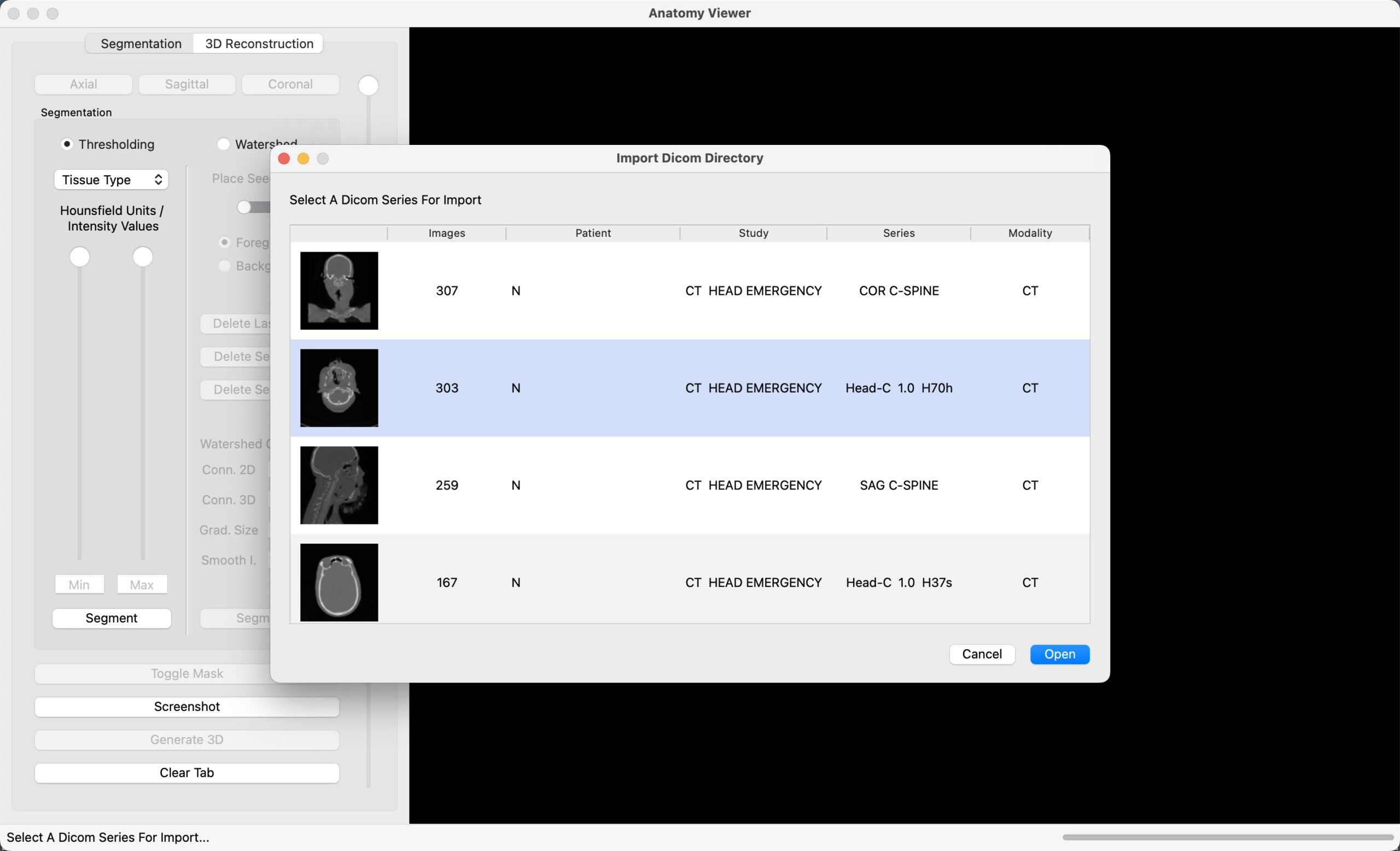
Select File -> Import Dicom Directory or File -> Import NIfTI, to import medical images. For the example below, a Dicom directory (folder) was selected. The images within the folder may belong to more than one series. The app automatically sorts the images into groups according to their respective Series IDs.
An image from each series, and the corresponding number of images, are grouped under the Dicom Series Label. This only happens with Dicom files. Select one of the presented options to load the Dicom series. In the example below, the series with 303 Images, is selected and highlighted in blue. Select Open, to load the chosen series.
The application will automatically detect the orientation of images, as they are loaded. Use the Axial, Sagittal and Coronal buttons to switch orientations, for a full 3D perspective of the medical scan.
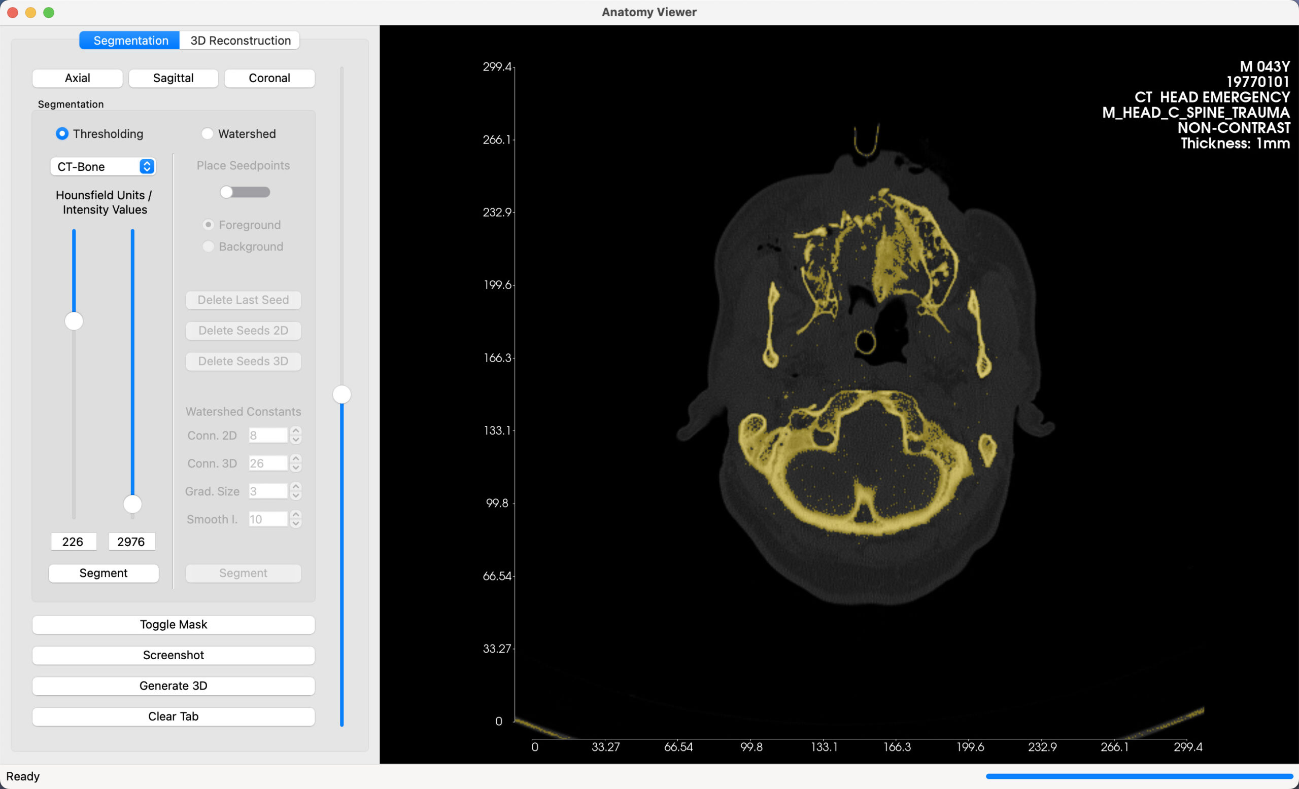
A summary of the patient information contained within the dicom files will be gleaned upon importation, and provided in the top right corner of the image window as in the example below. This includes the patient’s name, sex, age, birth date, study title, image properties and slice thickness.
You will also see two axes drawn on either side of the image, containing accurate measurements of the images.
If you wish to import a NIfTI file, the Images will be immediately loaded automatically upon selection. The steps described above, involving grouping images according to Series IDs would be skipped.
2. Choose Tissue Type
This step applies if you select Thresholding as the segmentation. It is selected by default. Region Growing will not be described in this example.
In this step, you choose what type of tissue you want to view in 3D. A drop down menu is provided on the top left, from which you can select what body tissue you are interested in. For the example above, CT Images are imported. Therefore the CT Presets are used.
Generation of 3D models is based on Hounsfield Units (HU) values. These values are explained in detail in the Hounsfield Units Page. In short, they are predetermined values that in general correspond to certain types of body tissue. The values come in pairs: Low and High HU values. These provide a threshold within which a particular body tissue can be found in CT Scan Images.
For example, Bone Tissue can generally be found within 226 and 2297 HUs. These numbers are not exact, and will not always produce identical results with different sets of CT Images, however, they may start as a baseline. Use Step 3 below to verify if you have properly isolated the body tissue that you want to view.
3. Create Mask Overlay on Images
Use the Segment Button to generate a 2D overlay on all CT Images, highlighting the tissue type selected in Step 2. In the example above, the mask highlights bone tissue picked out in each image. Use the slider to scroll through the scans, and verify if the Hounsfield Units selected accurately pick out the tissue you are interested in.
Adjust the HU values, to optimize the area picked out by the threshold, and select the Segment Button to recreate the overlay. Repeat this cycle, until you are satisfied with the mask.
Use the Toggle button to activate/deactivate the mask overlay.
Use the Screenshot button to export a PNG Image from the Image Window.
4. Generate 3D Model
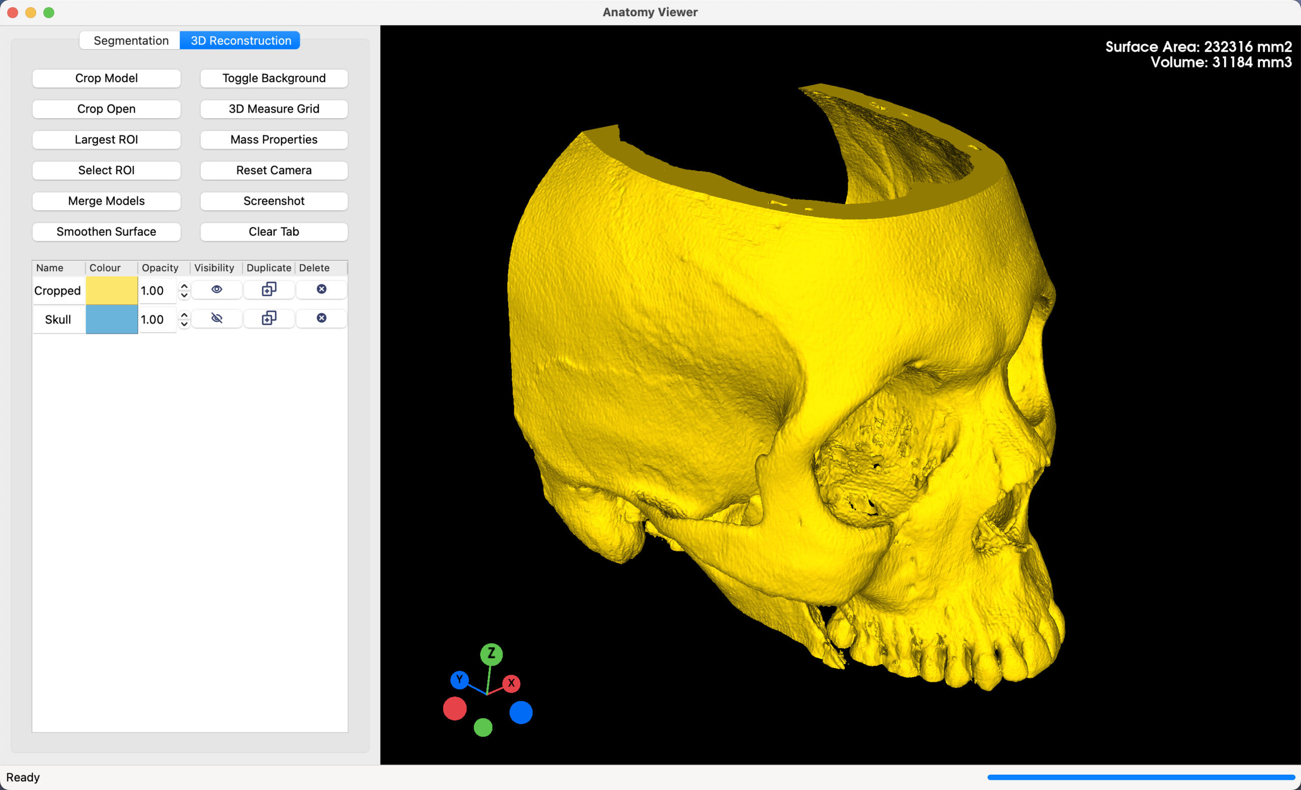
Once you are satisfied with the 2D Mask, select the Generate 3D Button to create a 3D Model. This 3D model is derived directly from the mask created in Step 3. Once generated, the active tab automatically switches to 3D Reconstruction. Here, all 3D Editing functions can be found. The 3D window is controlled either by mouse, or by touchpad. These controls are explained in detail in the 3D Controls Page.
Finishing Tools
Anatomy Viewer provides 3D finishing tools, ideal if you wish to export 3D Models for further analysis or to create physical models, via methods such as 3D Printing. By default, every 3D model generated within the app passes through a ‘Fill Hole‘ operation. This function, ensures that the surface of the 3D model is watertight. As the name suggests, it ensures there are no holes/gaps on the surface, and is a requirement for models intended for 3D printing. The functions described below are optional, and can further help prepare your model for production.
- Smooth: This option is fairly straightforward. Depending on the density of the slices in the Imported Images, the 3D Model may contain more detail than is necessary. When selected, the finishing process will smooth the surface of the 3D Model. This step can be repeated several times, until the surface is to your liking. However, too many smoothing repetitions may eventually reduce the accuracy of the model as small details are lost.
- Reduce: This option is slightly similar to the Smooth function as it reduces the complexity of the 3D model. This function reduces the number of points used to generate the 3D surface. The greater the number of points, the greater the detail of the 3D Model, and vice versa. This option is useful with models that have more detail than is necessary. The greater the complexity, the greater the file size of exported models. Exported model size can range from 10 MB to 1GB depending on the complexity of the 3D model.
Once you have selected the finishing options that you want, click the Finish Surface Button to initiate the process. The finishing process can be repeated, until you are satisfied with the your final Anatomical Model.
Useful Tools
- Toggle Background: Alternate between a Black (default), and white background for the 3D Window.
- 3D Measure Grid: Creates a 3D Bounding Box of the visible model in the 3D Reconstruction Window. The Measure Grid is marked with accurate measurements derived from the 3D coordinates of the images used to generate the model.
- Mass Properties: When selected, the surface area and volume of the 3D model are calculated, and the results presented in the top right corner of the window.
- Screenshot: Export a PNG Image of the 3D Model.
- Merge Models: Combine the selected models in the 3D window into one.